Problem Description
Create a graphical simulation of a simple four-bar
mechanical linkage.
Background & Techniques
Simulations of real world devices that move are some of the most
challenging projects I have undertaken. This is especially true if the
parts of the device interact with each other. A mechanical
linkage is a good example. This program, Four-bar Linkage Version 3,
is almost as simple as a linkage can be but with enough features to make it
interesting to play with.
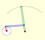
The linkage implemented has two fixed pivot points (connected by an
implied rod) with a pivoting rod attached to each fixed point. The two
pivoting rods are connected by the 4th rod. If the short pivot rod is
rotated and the long pivot rod extended, the result is a simple windshield
wiper model.
The program user can click and drag any of the rod end points to to vary
how the points move as the first rod rotates. Right clicking on any
rod end allows a trace of that point to be turned on or off. Buttons
allow linkage definitions to be saved and loaded and an animation of the
linkage movement to
started or stopped. A sliding bar allows control of the speed and
direction.
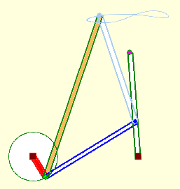
A second variation, included in the download samples, adds two more bars to form a "truss" with the
connecting rod, the tip of which will trace out some interesting patterns as
the driving rod rotates.
There are additional configurations and movement options that will
(might) be added to this initial checkpoint version to make it
more generalized. See the "Further Explorations" section at the
bottom of the page.
Non-programmers are welcome to read on, but may
want to skip to the bottom of this page to download
executable version of the program.
Notes for programmers
A TLinkage class derived from TPaintbox provides the
drawing space. TRod and TConnection classes work
together to define the linkage. The rods are kept in TLinkage
in an array. The connections are kept as objects in a TConnections
class derived from a sorted Tstringlist with connection ids as
the key field. Each rod object contains an array of the ids of
connection points on that rod.
The OnPaint exit of TLinkage clears the screen and repaints the
entire linkage each time the image must be redrawn. After updates,
i.e. when a connection point is moved or the animation moves the driver rod
by a small step, a call to TLinkage.Invalidate forces the redraw.
ONMouseDown, OnMouseMove, and OnMouseUp event exits for
TLinkage handle user changes to the linkage definition. The TForm
DoubleBuffered property is set to True to force updates to be
made off-screen and ensure flicker-free updating.
Tracing, drawing a trail of the path taken by a connection point, was one
of the trickier items to implement. When the MovementType
property of a connection is set to Trace, an array of the points
traversed is kept within the TConnection object. To prevent the array
size from growing without limit, a check is made and adding new points stops
(the TraceComplete property is set to True), when then the two
most recent traced points match the first two entries in the TracePoints
array.
Connection locations, the Loc property in TConnection, and the
current rod endpoints (P1, and P2 rod ends in TRod) are all
kept in TRealPoint format. This was necessary to ensure that
the paths would be retraced exactly as the linkage animation runs.
It does mean extra processing is required to convert floating point
coordinate values to integer format as they are drawn but it doesn't seem to
be a major consideration - no need to run the simulation super fast anyway.
File streams were used to save and restore linkage definitions. A
file stream, as the name implies, is a river of data in which each variable
is written as a series of bytes together with the number of bytes written.
There is no indication of the variable type or identification.
Retrieving such a data stream requires that the retrieval routines duplicate
exactly the variable order and sizes used by the generating routines.
For this reason, I recommend including a version identifier as the 1st field
in the stream so that future changes to the structure of the data can be
detected and multiple version handled correctly at retrieval time.
Writing and retrieving strings requires some special considerations
reflected in the WriteStr procedure and the ReadStr function
included in the ULinkage unit along with TLinkage and related
classes.
I feel that future enhancements to allow more generalized placement of
rods and connections will require a pre-run analysis of the definition to
identify the structural elements; connection loops which define structures
that we know how to move mathematically. The two implemented
here would the 4-bar loop with three connection point locations known, and
the 3-bar truss structure with two points known. There may be others,
only further play-time investigations will tell J.
Running/Exploring the Program